5G Security Architecture Overview
The 5G security architecture is a set of related trust relationships across the device, access network, serving core, home network, and external services. Each relationship has its own endpoints, credentials, protection mechanisms, and state.
This reference explains how to read that system model. It connects the security functions to the interfaces and traffic they protect, then shows how those relationships change with access type, roaming, and mobility. Use the architecture hub to explore individual topics and the general security overview for authentication and security-mode message details.
Quick facts
| Primary question | Which entities share a security relationship, and where does its protection end? |
|---|---|
| System scope | 5GS with NR connected to 5GC as the primary example |
| Architecture baseline | 3GPP TS 33.501 V18.8.0, Release 18 |
| Home responsibilities | Subscription credentials, identity de-concealment, and home authentication processing |
| Serving responsibilities | Access coordination, serving security anchor, and NAS context |
| Radio security | UE–gNB protection; PDCP applies RRC and configured user-plane protection |
| Network security | Separate protection and authorization for network interfaces, NF services, and operator interconnects |
Scope: a functional architecture, not a deployment inventory
A functional architecture shows responsibilities and relationships. It does not require each function to run on a separate appliance, nor does it show every transport gateway, proxy, certificate authority, or management system in an operational network. A security assessment must eventually map the logical functions to the actual deployment.
The primary example here is ordinary subscription-based access to the 5G Core (5GC) using NR. The baseline is TS 33.501 V18.8.0, Release 18, consistent with the other security references in this section. The architecture includes other access types, but EPC-anchored NSA, emergency access, non-public networks, and interworking require their specific procedures and assumptions.
Read a security relationship using five attributes: participants, protected information, trust material, protection endpoint, and context lifetime. This avoids treating “the network is secure” as a single state. A connection can have working radio protection while a separate core service request fails authorization.
The system map: device, access, serving network, and home network
The UE and its subscription module provide the device side of access security. The access network connects that device to the serving core. The serving network coordinates access and mobility, while the home network holds the subscription relationship and performs home authentication responsibilities.
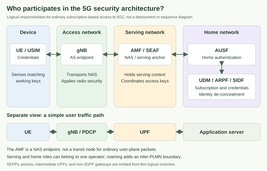
The gNB appears in both control-plane and user-plane paths, but its responsibilities differ from the AMF’s. The gNB terminates NR access-stratum security; the AMF terminates NAS security. The UPF handles user-plane forwarding and is not the endpoint of radio PDCP ciphering.
Home and serving roles do not imply different operators in every connection. In a non-roaming case, both can belong to the same operator. In roaming, the serving role is in the visited PLMN, and communication with the home PLMN crosses an operator boundary. The home network remains the home of the ordinary subscription credentials.
References: TS 33.501, clauses 4 and 6.1; TS 23.501.
Security domains and what they organize
TS 33.501 groups security features into domains. These domains describe scopes of protection rather than a strict stack of protocols. Network access security concerns the UE’s access relationship; network domain security concerns network entities communicating with one another. Those scopes can both participate in the same registration.
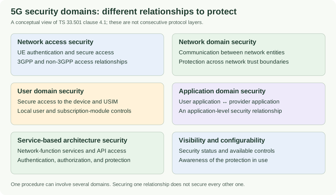
User domain security concerns secure access to the device and subscription module. Application domain security concerns the user application and its provider. Service-based architecture security addresses network-function services, and visibility and configurability concern awareness and control of security features. Application protection and local device controls cannot be inferred from a successful NAS Security Mode exchange.
A trust zone is a deployment boundary with particular trust assumptions. An operator can have several such zones. A security context is the state needed for a particular security relationship. These terms answer different questions: the domain identifies the feature scope, the zone identifies a trust boundary, and the context identifies the operational state.
Reference: TS 33.501, clauses 4.1, 5.9.1, and 5.10.
Home and serving responsibilities
Authentication distributes responsibilities without distributing the subscriber’s long-term secret to every node. The home network supports authentication and identity processing; the serving network obtains the material it needs for the serving relationship. Derived access material then supports the gNB’s narrower radio role.
| Role | Responsibility | What it does not imply |
|---|---|---|
| UE / USIM | Holds subscription credentials and participates in authentication; the UE maintains corresponding access and NAS contexts. | Every key and protocol operation resides inside the USIM. |
| UDM / ARPF / SIDF | Subscription handling, authentication credential processing, and de-concealment of the subscription identity. | The serving network receives the long-term subscription secret. |
| AUSF | Home authentication processing and support for establishment of the serving anchor. | AUSF terminates NAS or user-plane radio protection. |
| AMF / SEAF | NAS endpoint and serving Security Anchor Function; coordination of access security material. | AMF forwards ordinary application user-plane packets. |
| gNB | Radio security endpoint, AS algorithm selection, and PDCP protection. | Transporting NAS makes the gNB the NAS security endpoint. |
| SMF / UPF | Session-related security policy and user-plane handling, including applicable perimeter functions. | The UPF shares the UE–gNB radio ciphering context. |
ARPF means Authentication credential Repository and Processing Function; SIDF means Subscription Identifier De-concealing Function. These are functional responsibilities, not instructions to deploy a separate server for every label. Detailed node descriptions remain in the existing core-network reference.
Reference: TS 33.501, clauses 4.3, 6.1, 6.2, and 6.12. Continue with Security Entities.
Trust boundaries and interfaces
A line between two functions is not sufficient to explain its security. Identify whether the line represents a logical signaling interface, an actual transport connection, a service invocation, or the path of a user packet. Then identify the protection that applies to that relationship.
| Relationship | Security interpretation | Additional boundary to inspect |
|---|---|---|
| N1: UE–AMF | Logical NAS relationship, with its own keys, algorithms, and counters. | RRC and NGAP carry NAS along the access path; their transport is a separate concern. |
| NR Uu: UE–gNB | Access-stratum protection applied at PDCP for the relevant bearers. | Radio security does not automatically protect the gNB’s backhaul. |
| N2 / N3 | RAN–core signaling and user-plane transport respectively. | Applicable network-domain protection and actual security-gateway placement. |
| Service-based interfaces | NF service consumer–producer relationship with transport/message protection and authorization. | Proxy hops and service identity may differ from the immediate transport peer. |
| N32 | Service-based inter-PLMN signaling protection between SEPPs. | Roaming user-plane protection is outside this signaling relationship. |
| N9 between visited/home UPFs | User-plane interconnect in a home-routed roaming arrangement. | GTP-U perimeter controls and transport security, evaluated separately. |
Physical proximity is not a substitute for a trust model. Network functions in the same data center can belong to different trust zones, and a remote link can use a protected security association. The architecture review needs the operator’s actual zone boundaries and the mechanisms applied to traffic crossing them.
References: TS 33.501, clauses 5.9.1, 9, and 13; TS 33.210.
Control-plane and user-plane protection are different views
Control-plane messages establish and maintain network state. User-plane traffic carries the application’s data. A successful signaling procedure can configure user-plane security, but it does not make the signaling endpoint an endpoint for application data protection.
Signaling view
Non-Access-Stratum (NAS) security applies between the UE and AMF. Access-Stratum (AS) security applies to the radio relationship, with the gNB as the NR network endpoint. RRC SecurityMode and NAS Security Mode are separate procedures. On N2, the gNB and AMF exchange access-network signaling; carrying a protected NAS container does not protect every other field in the transport message using the NAS key.
User-plane view
A packet can be protected over the radio, over an operator transport segment, and by an application protocol at the same time. Each mechanism has its own endpoints and state. Radio ciphering can terminate at the gNB while an application TLS payload remains encrypted toward its server.
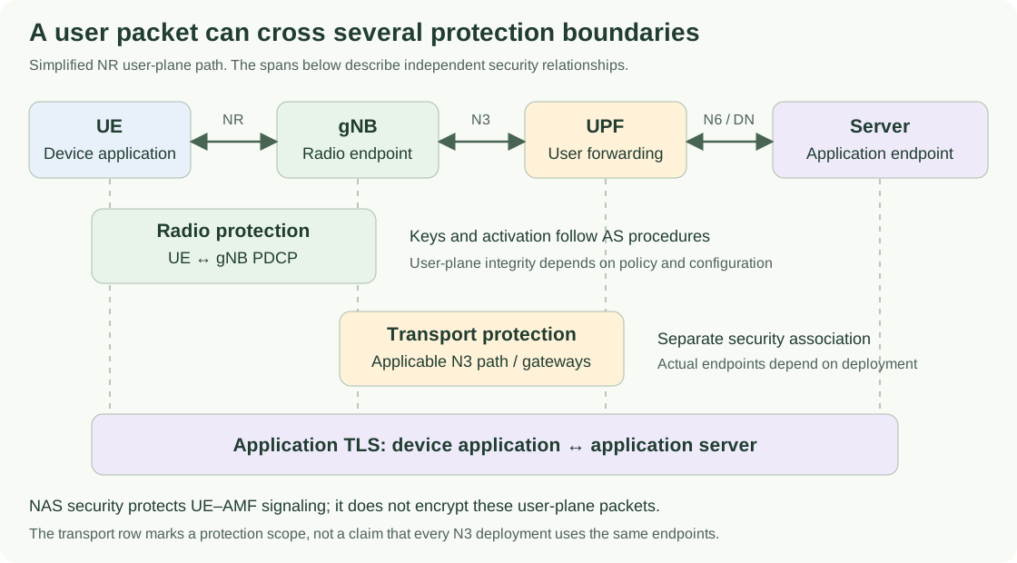
User-plane integrity also differs from signaling integrity. Check the configured data bearer and user-plane security policy rather than inferring its protection from RRC security success. Null ciphering, where selected, supplies no confidentiality even though the protocol has entered a ciphering state.
References: TS 33.501, clauses 6.4–6.7 and 9; TS 38.323, clauses 5.8–5.9. Continue with NAS and AS Security.
Identity, credentials, and keys answer different questions
An identifier names the subscription or context. A credential supports proof of the subscription relationship. A working key protects a particular exchange. These concepts are connected but not interchangeable: knowing a subscriber identity does not provide its authentication credential or access security keys.
SUPI is the permanent subscription identifier. SUCI is its concealed representation under the selected scheme, while 5G-GUTI supports temporary identification. The home SIDF performs SUCI de-concealment. A non-null scheme protects the relevant subscriber-specific identity information; it does not hide all routing fields. The null scheme does not provide cryptographic concealment.
For ordinary AKA-based authentication, the long-term secret remains in the subscription credential environments. Authentication-derived material feeds K_AUSF, K_SEAF, and K_AMF; narrower branches provide NAS keys and access-specific keys. The gNB needs access material such as K_gNB and its working-key derivatives, not the subscriber’s long-term secret or NAS working keys.
This separation limits the scope of distributed material. It also explains why the network-side role holding a key is useful evidence during troubleshooting: a NAS integrity mismatch belongs to a different context from a radio bearer integrity mismatch. Context identifiers such as ngKSI help select state; they are not cryptographic keys.
Reference: TS 33.501, clauses 6.1–6.2 and 6.12, Annexes A and C. Continue with Identity and Privacy, Authentication Architecture, and Key Hierarchy.
How access and deployment models change the picture
| Model | What changes | What to verify |
|---|---|---|
| NR access to 5GC | gNB supplies the radio security endpoint; AMF supplies the NAS endpoint. | Separate NAS and AS activation, keys, counters, and bearer policy. |
| Untrusted non-3GPP access | N3IWF supplies the defined access gateway role with IKEv2/IPsec-based establishment. | The access-security association and the UE–AMF NAS context. |
| Trusted non-3GPP access | A different access model and procedure applies, including TNGF. | The trusted-access procedure, gateway role, and access-specific keys; trust is not permission to omit security. |
| Roaming | Serving and home functions are separated across PLMNs. | Home authentication, interconnect protection, and home-routed versus local-breakout user traffic. |
| Split gNB | Logical gNB functions are distributed across CU/DU and potentially CU-CP/CU-UP components. | Actual PDCP placement, F1/E1 protection, and key handling within the RAN. |
| EPC-anchored NSA | The core anchor is EPS rather than the ordinary 5GS model used here. | EPS security and the applicable dual-connectivity/interworking procedures. |
The primary authentication method and the access security mechanism are separate choices. EAP-AKA′ is not simply another name for Wi-Fi security; EAP-5G in untrusted non-3GPP establishment is also distinct. Label the access gateway and the actual method before interpreting an EAP exchange.
Reference: TS 33.501, clauses 5.3, 6.1, 7, 7A, and 8. Continue with Non-3GPP Access Security.
Core services and interconnect have their own trust relationships
In the service-based core, distinguish the NF service consumer, service producer, discovery or authorization function, and any proxy. The immediate transport peer may not be the ultimate service consumer or producer. A diagram that collapses all those roles into “SBI” can hide an important authorization boundary.
Transport protection, peer authentication, and service access authorization answer different questions. TLS-based protection and OAuth 2.0 authorization appear in the applicable 5GC procedures, but neither the existence of a subscriber context nor transport encryption alone proves that a caller is allowed to invoke a particular NF service. Inspect identity, scope, audience, and the selected communication model where relevant.
Across PLMNs, SEPP protects service-based control-plane interconnect over N32. User-plane perimeter handling is separate: IPUPS is UPF functionality for GTP-U security on N9 between visited and home UPFs. NDS/IP addresses applicable network-layer protection and security gateways. These are different scopes, not alternative names for the same security mechanism.
References: TS 33.501, clauses 4.2, 5.9, 13.3, and 13.4; TS 33.210. Continue with Perimeter Security, Roaming and Interconnect Security, and Network Domain Security.
The architecture changes state even when the topology stays the same
A diagram shows where functions are, but a security context also has a lifetime. Authentication establishes material; activation selects the context and algorithms for use; later mobility, resume, or recovery can retain, transfer, or derive state according to the procedure.
NAS and AS context lifetimes are not identical. Releasing a radio connection does not necessarily erase the NAS relationship. RRC inactive can retain access context, and handover can derive target access keys without repeating full primary authentication. A move to another AMF introduces different context-handling questions from a move between radio cells.
For every context, identify its owner, key-set identifier where applicable, selected algorithms, counters, creation point, last update, and conditions for reuse or removal. A topologically correct diagram can still be operationally incomplete if it omits which version of that state is active.
References: TS 33.501, clauses 6.8–6.11; TS 24.501, clause 4.4; TS 38.331, clauses 5.3.7 and 5.3.13. Continue with Security Context Lifecycle.
Worked architecture examples
Example 1: fresh registration over NR
Assume ordinary subscription-based access with no reusable security context. First locate the UE, gNB, serving AMF/SEAF, and home AUSF/UDM roles. The gNB transports the UE’s NAS signaling; identity and authentication processing involve the serving and home roles. Once authentication-derived material is available, NAS Security Mode establishes the UE–AMF protection state, and the access context supports separate RRC security activation.
If the NAS command is rejected, inspect the UE–AMF context, selected algorithms, and capability checking. If the subsequent RRC command fails, inspect the gNB’s access context and radio exchange. The same registration contains both relationships, but they do not share one Security Mode procedure. See Initial Registration, NAS Security Mode, and AS Security Activation.
Example 2: encrypted application traffic after registration
Assume a configured data radio bearer and an application using TLS. At the radio boundary, PDCP handles the applicable user-plane protection. At the gNB, that radio protection ends; a separate protected transport segment may carry traffic toward the core. The application TLS payload can remain encrypted through the gNB and UPF until it reaches the application endpoint.
An opaque payload at a core capture point is therefore not proof that radio ciphering extends to the UPF. Conversely, valid NAS integrity tells you nothing by itself about the application’s TLS session. Identify the capture point and which layer the decoder has removed before interpreting visibility of the packet.
Example 3: a failure seen only in roaming
Keep the subscriber’s home authentication relationship separate from the inter-PLMN transport and service relationship. Establish whether the home authentication result was obtained, whether the relevant service request passed interconnect protection and authorization, and whether the symptom is actually in user traffic. A successful SEPP relationship does not prove that a home-routed N9 user-plane path is healthy.
How to read an implementation diagram or trace
- Identify the system anchor. Confirm 5GC versus EPC and the actual access type.
- Separate functional roles from hosts. Map AMF/SEAF, AUSF, UDM functions, access gateways, proxies, and transport gateways to the deployment.
- Label each relationship. Identify NAS, RRC, user-plane transport, service invocation, or interconnect signaling.
- Mark protection endpoints. Distinguish the endpoint processing security from an intermediate node transporting protected content.
- Attach the relevant context. Include keys or credentials, algorithms, counters, authorization state, and the activation or update procedure.
- Choose the observation point. Correlate UE, RAN, AMF, and home-service logs using the appropriate identities and timing.
The resulting map should explain why each participant needs its security material and what happens when the relationship changes. For field-level analysis, continue with the NAS and RRC message libraries. Use the security troubleshooting reference for symptom-specific failure branches.
Specification references
The pinned Release 18 editions make the clause references reproducible. They are the baseline for this article, rather than a claim to be the latest editions. The diagrams are explanatory views and omit the branches noted in their captions; the specifications define the complete conditions and procedures.
- 3GPP TS 33.501 V18.8.0 — Security architecture and procedures for 5G System
Release 18 baseline. Clause 4: domains, perimeter, and entities; 5.9: core trust boundaries; 6.1: primary authentication; 6.2 and Annex A: keys; 6.4–6.7: NAS, RRC, user-plane protection, and activation; 6.8–6.12: lifecycle and privacy; 7/7A: non-3GPP access; 9: interfaces; 13: service-based and interconnect security.
- 3GPP TS 23.501 — System architecture for the 5G System
System functions, reference points, access types, and roaming arrangements. This directory contains published editions; select the release and version appropriate to the network.
- 3GPP TS 24.501 V18.9.0 — NAS protocol for 5GS
Clause 4.4: NAS contexts, integrity, ciphering, and COUNT; 5.4.1: authentication; 5.4.2: security mode control; 5.4.3: identification.
- 3GPP TS 38.331 V18.4.0 — NR RRC protocol specification
Clause 5.3.4: initial AS security activation; 5.3.5.7: AS security key update; 5.3.7: re-establishment; 5.3.13: resume.
- 3GPP TS 38.323 V18.4.0 — NR PDCP specification
Clauses 5.8–5.9: ciphering, deciphering, integrity protection, and verification at the radio security endpoint.
- 3GPP TS 33.210 — Network Domain Security; IP network layer security
Companion framework for network-domain protection and security gateways. The directory provides the published editions.
Frequently asked questions
What is the starting point for understanding 5G security architecture?
Identify the communicating entities and the endpoints of each security relationship. Then determine the identity or credential being verified, the keys and context used, and the procedure that activates or changes that context.
Are home and serving networks always different operators?
No. Home and serving are functional roles. They may belong to the same operator in a non-roaming case. Roaming separates the serving role into a visited network and introduces inter-PLMN communication and perimeter protection.
Why does a gNB carry NAS without terminating NAS security?
NAS is logically exchanged between the UE and AMF. The gNB transports it using access-network signaling while maintaining its own UE–gNB access-stratum security context. Transporting a message does not make a function its cryptographic endpoint.
Does NAS security encrypt user-plane IP traffic?
No. NAS protection applies to UE–AMF signaling. User-plane packets use the applicable radio bearer protection, network transport protection, and application security, each with different endpoints and security state.
Does a security domain correspond to one physical network segment?
Not necessarily. Security domains organize the features and relationships being protected. A deployment can contain multiple trust zones within one operator, and one procedure can involve several security domains.
Does a valid subscriber context authorize network-function API calls?
No. Subscriber access security and network-function service authorization are separate relationships. The calling network function, transport or message protection, service scope, and applicable authorization mechanism must be evaluated independently.