5G Connected Mode Handover Explained
Introduction
In 5G networks, Connected Mode Handover allows a User Equipment (UE) to move between cells while maintaining an active RRC connection.
Unlike Idle Mode Mobility, where the UE performs mobility decisions itself, handover decisions in connected mode are controlled by the network.
The purpose of connected mode handover is to:
- maintain uninterrupted data sessions
- prevent radio link failures
- optimize network performance
This procedure is defined by the 3rd Generation Partnership Project in:
- 3GPP TS 38.300 - NR Overall Description
- 3GPP TS 38.331 - RRC Protocol
- 3GPP TS 23.502 - 5G System Procedures
When Connected Mode Handover Happens
A handover occurs when:
- the UE moves away from the serving cell
- a neighboring cell offers better signal quality
- the network needs to balance load
Typical triggers include:
- RSRP degradation
- interference conditions
- cell congestion
Types of Handover in 5G
| Handover Type | Description |
|---|---|
| Xn Handover | Direct handover between gNBs |
| N2 Handover | Handover controlled by the core network |
| Intra-gNB Handover | Between cells within the same gNB |
Network Elements Involved
UE (User Equipment)
Measures signal quality and reports measurements to the network.
Source gNB
The currently serving base station controlling the UE.
Target gNB
The base station to which the UE will be transferred.
AMF
Participates in N2 handovers when core network coordination is required.
Interfaces Used
| Interface | Description |
|---|---|
| NR-Uu | Radio interface between UE and gNB |
| Xn | Interface between neighboring gNBs |
| N2 | Interface between gNB and AMF |
| N3 | User plane tunnel between gNB and UPF |
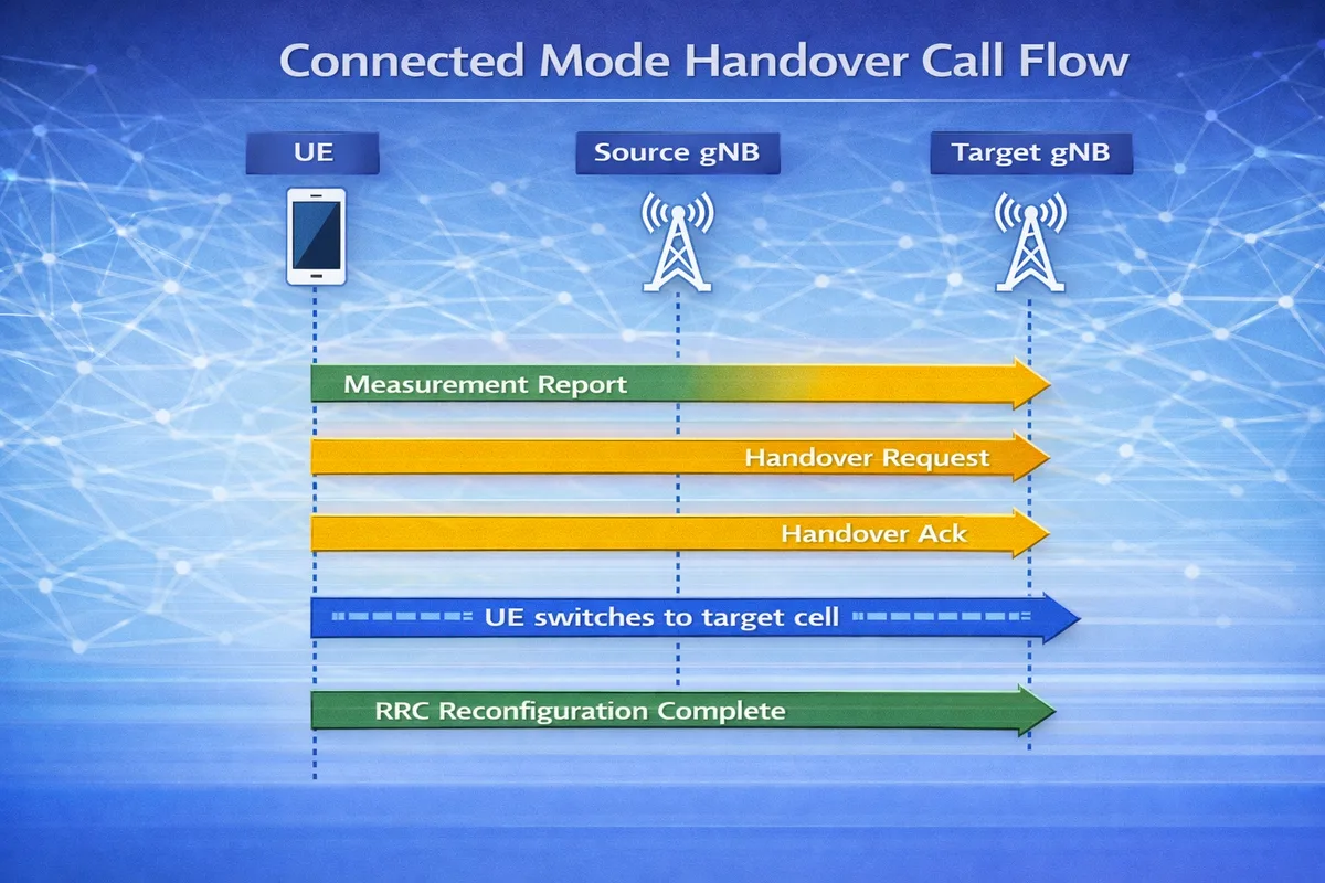
Connected Mode Handover Call Flow
Below is the simplified signaling sequence.
UE          Source gNB         Target gNB
 |              |                 |
 |--Measurement Report---------->|
 |              |                 |
 |              |--Handover Req-->|
 |              |                 |
 |              |<--Handover Ack--|
 |<--RRC Handover Command--------|
 |                               |
 |===== UE switches to target cell =====|
 |                               |
 |----RRC Reconfiguration Complete---->|
During this procedure, the UE switches from the source cell to the target cell without interrupting the data session.
Step-by-Step Explanation
Step 1: Measurement Reporting
The UE continuously measures signal quality of neighboring cells.
These measurements include:
- RSRP
- RSRQ
- SINR
The UE sends a Measurement Report to the serving gNB.
Important parameters to check
Engineers should verify:
- measurement event type (A3, A5, etc.)
- RSRP levels
- measurement thresholds
Step 2: Handover Decision
The source gNB analyzes the measurement report and decides whether a handover is required.
The source gNB selects the target gNB.
Important parameters to check
Check:
- neighbor cell configuration
- handover thresholds
- load balancing policies
Step 3: Handover Preparation
The source gNB sends a Handover Request to the target gNB via the Xn interface.
The target gNB prepares resources for the UE.
Important parameters to check
Verify:
- target cell resources
- radio bearer configuration
- security context transfer
Step 4: Handover Command
The source gNB sends an RRC Reconfiguration (Handover Command) to the UE.
The UE then:
- disconnects from the source cell
- synchronizes with the target cell
Important parameters to check
Check:
- target cell ID
- radio configuration parameters
- mobility control information
Step 5: Handover Completion
The UE connects to the target gNB and sends RRC Reconfiguration Complete.
User plane traffic continues through the target cell.
Data Path After Handover
Once handover completes, the data path becomes:
UE -> Target gNB -> UPF -> Data NetworkThe user session remains active, so applications do not experience interruption.
Handover Measurement Events
Common measurement events used in 5G handovers:
| Event | Description |
|---|---|
| A1 | Serving cell becomes better |
| A2 | Serving cell becomes worse |
| A3 | Neighbor cell becomes better than serving cell |
| A5 | Serving cell below threshold and neighbor above threshold |
Event A3 is the most commonly used trigger for handovers.
Troubleshooting Handover Problems
Handover Failure
Possible causes:
- incorrect neighbor configuration
- insufficient target cell resources
- radio interference
Radio Link Failure
Possible reasons:
- handover command lost
- UE unable to synchronize with target cell
- poor radio conditions
Ping-Pong Handover
Possible causes:
- incorrect threshold settings
- aggressive mobility parameters
- overlapping coverage
Key Messages in Connected Mode Handover
| Message | Purpose |
|---|---|
| Measurement Report | UE reports neighbor measurements |
| Handover Request | Source gNB requests target resources |
| Handover Command | UE instructed to move to target cell |
| RRC Reconfiguration Complete | UE confirms handover |
Relevant 3GPP Specifications
The handover procedure is defined by the 3rd Generation Partnership Project in:
- 3GPP TS 38.300 - NR Overall Description
- 3GPP TS 38.331 - RRC Protocol
- 3GPP TS 23.502 - 5G System Procedures
Summary
The Connected Mode Handover procedure enables a UE to move between cells while maintaining an active connection.
The process involves:
- UE measurement reporting
- handover decision by the source gNB
- resource preparation at the target gNB
- UE switching to the new cell
This procedure ensures seamless mobility and uninterrupted data sessions in 5G networks.