5G Inter-AMF Mobility Procedure Explained
Introduction
In 5G networks, Inter-AMF Mobility occurs when a User Equipment (UE) moves to an area served by a different Access and Mobility Management Function (AMF).
In such cases, the UE context must be transferred from the source AMF to the target AMF while maintaining the UE’s connectivity and mobility management.
This procedure ensures:
- continuous network registration
- seamless mobility across AMF regions
- uninterrupted data sessions
The procedure is defined by the 3rd Generation Partnership Project in:
- 3GPP TS 23.502 - 5G System Procedures
- 3GPP TS 23.501 - System Architecture
- 3GPP TS 24.501 - NAS Protocol
When Inter-AMF Mobility Happens
Inter-AMF mobility typically occurs when:
- the UE moves into a different AMF service area
- the UE performs mobility registration update
- the network reassigns the UE to another AMF
Typical scenarios include:
- inter-region mobility
- load balancing between AMFs
- roaming scenarios
Network Functions Involved
UE (User Equipment)
Initiates the mobility update when entering a new registration area.
Source gNB
The base station currently serving the UE.
Target gNB
The base station serving the UE after mobility.
Source AMF
The current mobility management entity responsible for the UE.
Target AMF
The new AMF that takes over mobility management for the UE.
Interfaces Used
| Interface | Description |
|---|---|
| NR-Uu | Radio interface between UE and gNB |
| N2 | Interface between gNB and AMF |
| N8 | Interface between AMFs |
| N11 | Interface between AMF and SMF |
Inter-AMF Mobility Call Flow
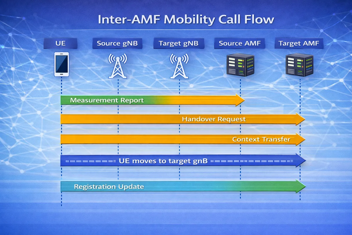
Below is the simplified signaling sequence.
UE        Source gNB      Target gNB      Source AMF      Target AMF
 |            |               |              |               |
 |--Measurement Report------>|              |               |
 |            |--Handover Request---------->|               |
 |            |               |              |--Context----->|
 |            |               |              |               |
 |<--RRC Handover Command----|              |               |
 |====== UE moves to target gNB ======|
 |            |               |              |               |
 |----Registration Update------------------------------>|
 |                              |              |<--Context|
 |                              |              | Transfer |
 |                              |              |----------|
 |<--Registration Accept--------------------------------|
During this procedure, the UE moves to a new AMF while maintaining its session context.
Step-by-Step Explanation
Step 1: Measurement Reporting
The UE measures neighboring cells and reports measurements to the source gNB.
These measurements include:
- RSRP
- RSRQ
- SINR
Important parameters to check
Engineers should verify:
- measurement event triggers
- neighbor cell configuration
- signal quality thresholds
Step 2: Handover to Target gNB
The source gNB initiates a handover procedure to the target gNB.
If the target gNB belongs to a different AMF region, inter-AMF mobility will be triggered.
Important parameters to check
Check:
- target gNB configuration
- AMF region mapping
- neighbor relationships
Step 3: AMF Context Transfer
The source AMF transfers the UE context to the target AMF.
The context includes:
- UE identity
- security parameters
- mobility context
- session information
Important parameters to check
Verify:
- UE context transfer success
- security key continuity
- session management context
Step 4: Registration Update
The UE performs a Mobility Registration Update with the target AMF.
This step ensures that the UE is now managed by the new AMF.
Important parameters to check
Check:
- registration type
- UE identity (5G-GUTI / SUCI)
- tracking area list
Step 5: Registration Accept
The target AMF sends a Registration Accept message to the UE.
After this step:
- the UE is successfully registered with the new AMF
- mobility management continues normally
Data Path After Mobility
After inter-AMF mobility completes, the data path becomes:
UE -> Target gNB -> UPF -> Data NetworkUser sessions remain active during the mobility procedure.
Differences Between Inter-AMF and Inter-gNB Mobility
| Feature | Inter-gNB Handover | Inter-AMF Mobility |
|---|---|---|
| Base station change | Yes | Yes |
| AMF change | No | Yes |
| Context transfer | gNB-to-gNB | AMF-to-AMF |
| Complexity | Medium | Higher |
Troubleshooting Inter-AMF Mobility
Registration Update Failure
Possible causes:
- incorrect AMF configuration
- missing registration area configuration
- UE identity mismatch
Context Transfer Failure
Possible reasons:
- N8 interface connectivity issue
- AMF software mismatch
- security context transfer failure
Session Interruption
Possible causes:
- SMF session context mismatch
- UPF routing issues
- mobility configuration errors
Key Messages in Inter-AMF Mobility
| Message | Purpose |
|---|---|
| Measurement Report | UE reports signal measurements |
| Handover Request | Source gNB requests handover |
| Context Transfer | UE context transferred between AMFs |
| Registration Update | UE registers with target AMF |
| Registration Accept | Target AMF confirms mobility |
Relevant 3GPP Specifications
The Inter-AMF Mobility procedure is defined by the 3rd Generation Partnership Project:
- 3GPP TS 23.502 - 5G System Procedures
- 3GPP TS 23.501 - System Architecture
- 3GPP TS 24.501 - NAS Protocol
Summary
The Inter-AMF Mobility procedure enables a UE to move between different AMF service areas while maintaining connectivity.
The process includes:
- measurement reporting by the UE
- handover to the target gNB
- context transfer between AMFs
- mobility registration update
This ensures seamless mobility across different core network regions in 5G networks.