5G Inter-gNB Handover Procedure Explained
Introduction
In 5G networks, Inter-gNB Handover occurs when a User Equipment (UE) moves from one gNB (Next Generation NodeB) to another while maintaining an active connection.
This type of handover happens when the serving base station and the target base station belong to different gNB nodes.
The goal of this procedure is to:
- maintain uninterrupted data sessions
- preserve radio link quality
- ensure seamless user mobility
The procedure is defined by the 3rd Generation Partnership Project in:
- 3GPP TS 23.502 - 5G System Procedures
- 3GPP TS 38.300 - NR Architecture
- 3GPP TS 38.331 - RRC Protocol
When Inter-gNB Handover Happens
Inter-gNB handover typically occurs when:
- the UE moves out of the coverage area of the serving gNB
- a neighboring gNB provides better signal quality
- network load balancing requires UE relocation
Typical triggers include:
- decreasing RSRP
- increased interference
- network optimization policies
Network Elements Involved
UE (User Equipment)
Measures neighboring cell signals and reports them to the network.
Source gNB
The current serving base station managing the UE connection.
Target gNB
The neighboring base station that will take over the UE connection.
AMF (Access and Mobility Management Function)
Participates in the procedure if core network coordination is required.
Interfaces Used
| Interface | Description |
|---|---|
| NR-Uu | Radio interface between UE and gNB |
| Xn | Interface between neighboring gNBs |
| N2 | Interface between gNB and AMF |
| N3 | User plane interface between gNB and UPF |
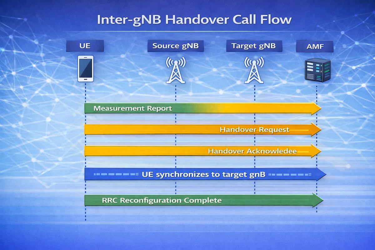
Inter-gNB Handover Call Flow
Below is the simplified signaling sequence.
UE           Source gNB        Target gNB        AMF
 |               |                 |              |
 |--Measurement Report----------->|
 |               |                 |              |
 |               |--Handover Request-------------->|
 |               |                 |              |
 |               |<--Handover Acknowledge---------|
 |<--RRC Handover Command----------|
 |                                 |
 |====== UE synchronizes to target gNB ======|
 |                                 |
 |----RRC Reconfiguration Complete---------->|
During this procedure, the UE moves from the source gNB to the target gNB while maintaining its data session.
Step-by-Step Explanation
Step 1: Measurement Reporting
The UE continuously measures neighboring cells.
Key measurements include:
- RSRP (Reference Signal Received Power)
- RSRQ (Reference Signal Received Quality)
- SINR
The UE sends a Measurement Report to the source gNB.
Important parameters to check
Engineers should verify:
- measurement event type (A3, A5)
- RSRP levels
- measurement thresholds
Step 2: Handover Decision
The source gNB analyzes the measurement report.
If a neighboring cell offers better signal quality, the source gNB decides to initiate handover.
Important parameters to check
Check:
- neighbor cell configuration
- handover offset values
- load balancing policies
Step 3: Handover Preparation
The source gNB sends a Handover Request to the target gNB.
The target gNB:
- allocates radio resources
- prepares context for the UE
Important parameters to check
Verify:
- radio bearer configuration
- UE context transfer
- security key forwarding
Step 4: Handover Command
The source gNB sends an RRC Reconfiguration message (Handover Command) to the UE.
This message instructs the UE to switch to the target cell.
Important parameters to check
Look for:
- target cell identity
- radio configuration parameters
- mobility control information
Step 5: Handover Completion
The UE synchronizes with the target gNB and sends RRC Reconfiguration Complete.
User plane traffic continues through the new base station.
Data Path After Handover
After handover completes, the data path becomes:
UE -> Target gNB -> UPF -> Data NetworkApplications continue running without interruption.
Differences Between Inter-gNB and Intra-gNB Handover
| Feature | Intra-gNB Handover | Inter-gNB Handover |
|---|---|---|
| Base station change | Same gNB | Different gNB |
| Signaling complexity | Lower | Higher |
| Interfaces used | Internal | Xn or N2 |
Troubleshooting Inter-gNB Handover
Handover Failure
Possible causes:
- insufficient resources in target cell
- incorrect neighbor configuration
- radio interference
Radio Link Failure
Possible reasons:
- UE cannot synchronize with target cell
- handover command lost
- poor signal conditions
Ping-Pong Handover
Possible causes:
- incorrect handover thresholds
- overlapping cell coverage
- aggressive mobility parameters
Key Messages in Inter-gNB Handover
| Message | Purpose |
|---|---|
| Measurement Report | UE reports neighboring cells |
| Handover Request | Source gNB requests target resources |
| Handover Acknowledge | Target gNB confirms preparation |
| RRC Handover Command | UE instructed to switch cell |
| RRC Reconfiguration Complete | UE confirms handover |
Relevant 3GPP Specifications
The Inter-gNB Handover procedure is defined by the 3rd Generation Partnership Project in:
- 3GPP TS 23.502 - 5G System Procedures
- 3GPP TS 38.300 - NR Overall Description
- 3GPP TS 38.331 - RRC Protocol
Summary
The Inter-gNB Handover procedure allows a UE to move between different 5G base stations while maintaining an active connection.
The process includes:
- measurement reporting by the UE
- handover decision by the source gNB
- resource preparation at the target gNB
- UE synchronization with the new cell
This ensures seamless mobility and uninterrupted user experience in 5G networks.