5G PDU Session Establishment Procedure Explained
Introduction
The PDU Session Establishment procedure in 5G networks allows a User Equipment (UE) to establish a data connection with an external data network such as the internet.
A PDU Session is the equivalent of a data bearer in LTE, enabling the UE to send and receive IP packets.
During this procedure:
- the UE requests a data session
- the network allocates IP connectivity
- QoS parameters are configured
- user-plane tunnels are created
The procedure is defined by the 3rd Generation Partnership Project in:
- 3GPP TS 23.502 - 5G System Procedures
- 3GPP TS 24.501 - NAS Protocol
What is a PDU Session?
A Protocol Data Unit (PDU) Session represents a logical connection between the UE and a Data Network (DN).
Examples of data networks include:
- the public internet
- private enterprise networks
- operator services
Each PDU session is associated with:
- a PDU Session ID
- a QoS flow
- a User Plane path
Network Functions Involved
The PDU Session Establishment procedure involves several core network components.
UE (User Equipment)
Initiates the PDU session request when an application requires data connectivity.
gNB
The gNB provides radio access and forwards control plane signaling.
AMF (Access and Mobility Management Function)
Handles signaling and forwards session requests to the SMF.
SMF (Session Management Function)
The SMF is responsible for:
- session creation
- IP address allocation
- QoS policy management
UPF (User Plane Function)
The UPF forwards user data packets between the UE and the data network.
Interfaces Used
| Interface | Description |
|---|---|
| NR-Uu | Radio interface between UE and gNB |
| N1 | NAS signaling between UE and AMF |
| N2 | Control signaling between gNB and AMF |
| N11 | Control interface between AMF and SMF |
| N4 | Control interface between SMF and UPF |
| N3 | User plane tunnel between gNB and UPF |
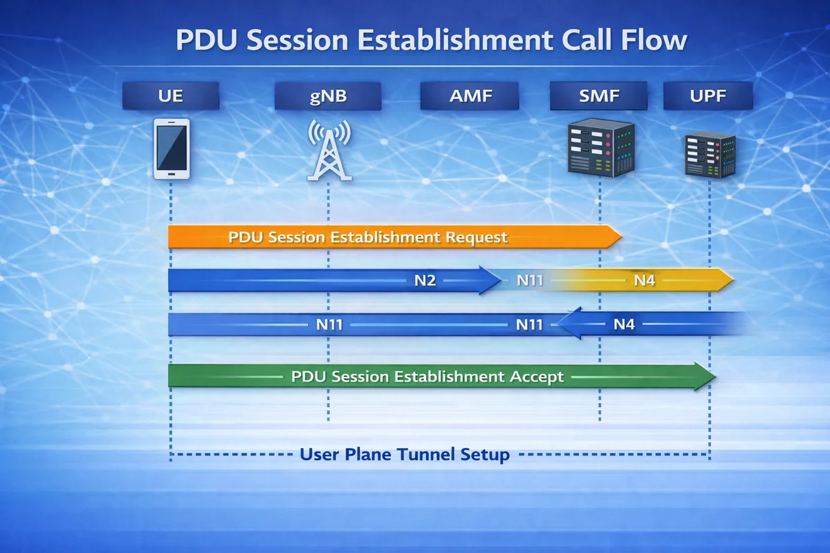
PDU Session Establishment Call Flow
Below is the simplified signaling sequence.
UE           gNB           AMF            SMF           UPF
 |            |             |              |             |
 |---PDU Session Establishment Request--->|
 |            |----N2--------------------->|
 |            |             |----N11----->|
 |            |             |             |----N4----->|
 |            |             |             |<---N4------|
 |            |             |<---N11------|
 |<--PDU Session Establishment Accept----|
 |            |                           |
 |===== User Plane Tunnel Setup ========>|
After this procedure completes, the UE can start sending IP traffic.
Step-by-Step Explanation
Step 1: PDU Session Establishment Request
The UE sends a PDU Session Establishment Request NAS message to the AMF.
The request contains:
- PDU Session ID
- requested data network (DNN)
- session type (IPv4 / IPv6 / Ethernet)
- requested slice (S-NSSAI)
Important parameters to check
Engineers should verify:
- PDU Session ID
- DNN (Data Network Name)
- requested S-NSSAI
- session type
Step 2: Session Management Request
The AMF forwards the request to the SMF via the N11 interface.
The SMF:
- validates subscription data
- selects a suitable UPF
- allocates an IP address for the UE
Important parameters to check
Check:
- SMF selection
- subscriber session limits
- IP address allocation
Step 3: UPF Configuration
The SMF configures the UPF using the N4 interface.
This includes:
- creating a user plane tunnel
- defining forwarding rules
- assigning QoS parameters
Important parameters to check
Verify:
- UPF selection
- forwarding rules
- QoS flow parameters
Step 4: PDU Session Establishment Accept
Once resources are allocated, the network sends PDU Session Establishment Accept to the UE.
The message contains:
- allocated IP address
- QoS parameters
- session configuration
Important parameters to check
Look for:
- assigned IP address
- QoS flow identifier
- session AMBR values
Step 5: User Plane Tunnel Activation
Finally, the N3 tunnel is established between the gNB and UPF.
This enables user data to flow through the network.
Data path after session setup
UE → gNB → UPF → Data NetworkAt this point, the UE can start sending application traffic.
Common PDU Session Types
| Session Type | Description |
|---|---|
| IPv4 | Standard internet connectivity |
| IPv6 | IPv6 data connectivity |
| IPv4v6 | Dual stack connectivity |
| Ethernet | Used in enterprise networks |
Troubleshooting PDU Session Failures
Session Establishment Reject
Possible causes:
- invalid DNN
- slice not allowed
- subscription restrictions
No IP Address Assigned
Possible reasons:
- SMF allocation failure
- UPF misconfiguration
- address pool exhaustion
Data Traffic Not Flowing
Possible causes:
- N3 tunnel failure
- QoS rule mismatch
- UPF routing issue
Key NAS Messages
| Message | Purpose |
|---|---|
| PDU Session Establishment Request | UE requests data session |
| PDU Session Establishment Accept | Network accepts session |
| PDU Session Establishment Reject | Session denied |
Relevant 3GPP Specifications
The PDU Session Establishment procedure is defined in:
- 3GPP TS 23.502 - 5G System Procedures
- 3GPP TS 24.501 - NAS Protocol
- 3GPP TS 38.300 - NR Overall Description
Published by the 3rd Generation Partnership Project.
Summary
The PDU Session Establishment procedure creates a data connection between the UE and a data network in 5G architecture.
It involves coordination between multiple network functions including:
- AMF
- SMF
- UPF
Once completed, the UE receives an IP address and can begin sending data through the 5G user plane.