5G Secondary PDU Session Setup Explained
Introduction
In 5G networks, a Secondary PDU Session is an additional data session established between the User Equipment (UE) and a Data Network (DN) while a primary PDU session already exists.
This allows the UE to connect to multiple data networks simultaneously.
For example, a UE may have:
- one PDU session for internet access
- another session for enterprise services
- another session for operator services
The procedure is defined by the 3rd Generation Partnership Project in:
- 3GPP TS 23.502 - 5G System Procedures
- 3GPP TS 24.501 - NAS Protocol
Why Secondary PDU Sessions Are Needed
Modern applications often require connectivity to multiple networks at the same time.
| Scenario | Description |
|---|---|
| Enterprise access | Secure connection to corporate network |
| IoT services | Separate network slice for device management |
| Network slicing | Different slices for different services |
| Private networks | Access to private enterprise infrastructure |
Using secondary PDU sessions, the UE can maintain multiple simultaneous data connections.
Network Functions Involved
Several 5G Core Network Functions participate in this procedure.
UE (User Equipment)
Initiates the secondary session request when a new network connection is required.
gNB
Provides radio connectivity and forwards signaling messages.
AMF (Access and Mobility Management Function)
Handles control-plane signaling and forwards session requests.
SMF (Session Management Function)
The SMF manages the creation of the secondary PDU session.
UPF (User Plane Function)
The UPF handles user plane traffic between the UE and the data network.
Interfaces Used
| Interface | Description |
|---|---|
| NR-Uu | Radio interface between UE and gNB |
| N1 | NAS signaling between UE and AMF |
| N2 | Control signaling between gNB and AMF |
| N11 | Control interface between AMF and SMF |
| N4 | Control interface between SMF and UPF |
| N3 | User plane tunnel between gNB and UPF |
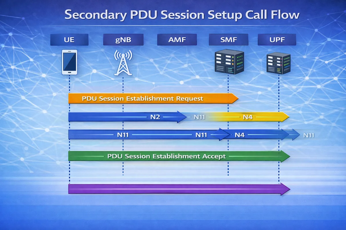
Secondary PDU Session Setup Call Flow
Below is the simplified signaling sequence.
UE           gNB           AMF            SMF            UPF
 |            |             |              |              |
 |--PDU Session Establishment Request---->|
 |            |----N2-------------------->|
 |            |             |----N11----->|
 |            |             |              |----N4----->|
 |            |             |              |<---N4-----|
 |            |             |<---N11------|
 |<--PDU Session Establishment Accept----|
Although the signaling looks similar to the primary PDU session establishment, the difference is that another session already exists.
Step-by-Step Explanation
Step 1: Secondary Session Request
The UE sends a PDU Session Establishment Request to create an additional session.
The message contains:
- new PDU Session ID
- requested Data Network Name (DNN)
- requested slice (S-NSSAI)
Important parameters to check
Engineers should verify:
- PDU session ID
- DNN
- S-NSSAI
- session type
Step 2: Session Management Processing
The AMF forwards the request to the SMF.
The SMF:
- verifies subscriber authorization
- selects a UPF
- allocates an IP address
Important parameters to check
Check:
- SMF selection
- subscription data
- slice authorization
Step 3: UPF Configuration
The SMF configures the UPF using the N4 interface.
The UPF creates:
- forwarding rules
- packet detection rules
- QoS enforcement rules
Important parameters to check
Verify:
- UPF selection
- QoS flow parameters
- forwarding rules
Step 4: Session Establishment Accept
The network sends PDU Session Establishment Accept to the UE.
The message contains:
- assigned IP address
- QoS parameters
- session configuration
Important parameters to check
Look for:
- PDU session ID
- QoS Flow Identifier (QFI)
- session AMBR
Step 5: User Plane Activation
Once configuration is complete, the user plane tunnel is activated.
Data can now flow through the secondary session.
Data Path After Setup
After the session is established, the data path becomes:
UE -> gNB -> UPF -> Data NetworkMultiple sessions may exist simultaneously.
Differences Between Primary and Secondary Sessions
| Feature | Primary PDU Session | Secondary PDU Session |
|---|---|---|
| First session | Yes | No |
| Data network | Default network | Additional network |
| Session ID | First allocated | New session ID |
| IP address | First IP assigned | Additional IP assigned |
Troubleshooting Secondary PDU Sessions
Session Establishment Rejected
Possible causes:
- subscription restrictions
- slice mismatch
- DNN not allowed
No IP Address Assigned
Possible reasons:
- SMF configuration error
- address pool exhaustion
- UPF selection failure
Data Traffic Not Flowing
Possible causes:
- N3 tunnel failure
- QoS mismatch
- routing configuration issue
Key NAS Messages
| Message | Purpose |
|---|---|
| PDU Session Establishment Request | UE requests new session |
| PDU Session Establishment Accept | Network accepts session |
Relevant 3GPP Specifications
This procedure is defined by the 3rd Generation Partnership Project in:
- 3GPP TS 23.502 - 5G System Procedures
- 3GPP TS 24.501 - NAS Protocol
- 3GPP TS 38.300 - NR Architecture
Summary
The Secondary PDU Session Setup procedure allows a 5G device to connect to multiple data networks simultaneously.
This enables:
- enterprise connectivity
- network slicing
- advanced multi-service applications
Secondary PDU sessions are an important feature of flexible service delivery in 5G architecture.