Though RLC (Radio Link Control) layer in LTE is similar to that of UMTS, but still there are some significant differences. One of the big change is RLC LTE header structure for different PDU (Protocol Data Unit) types.
When it comes to LTE, RLC can have the following PDU types
- RLC TMD PDU
- RLC UMD PDU
- RLC AMD PDU
- RLC AMD PDU Segment
- RLC Status PDU
In this tutorial i will explain details about TMD PDU, UMD PDU, AMD PDU AMD PDU Segment and STATUS PDU.
Transparent Mode Data PDU (TMD PDU)
As the name suggests the Transparent mode entity in RLC does not add any overhead to the upper layer SDUs. The entity just transmit the SDUs coming from upper layer to MAC.
The RLC TM SDUs are byte aligned and so the PDUs. There is no header for RLC TMD PDU.
RLC TM is used for transmission of paging messages on PCCH, system informations transmitted on BCCH and SRB0 messages transmitted on CCCH.
Unacknowledged Mode Data PDU (UMD PDU)
LTE RLC Unacknowledged Mode is used for transmission of delay sensitive packets, such as VoIP packets or audio/video streams. RLC UM always has PDCP as upper layer and only DTCH is used as logical channel.
UMD PDU header consists of a fixed part and an extension part. The fixed part of the header has a FI, an E and a SN field. The extension part consists of E(s) and LI(s).
NOTE: Both the fixed and extension part of UMD PDU are byte aligned.
Also it should be noted here that the SN (Sequence Number) field in UMD PDU header can be 5 bits or 10 bits long. When the header is 5 bits ling the fixed part of UMD PDU header is 1 byte long. When 10 bits SN is used the fixed part is 2 byte long and the first three bits of the header are R1 (Reserved) fields. R1 is always set to 0.
The extension part of UMD PDU has E(s) and LI(s). An UMD PDU header consists of an extension part only when more than one Data field elements are present in the UMD PDU, in which case an E and a LI are present for every Data field element except the last. Furthermore, when an UMD PDU header consists of an odd number of LI(s), four padding bits follow after the last LI.
UMD PDU Header (No LI) – 5 bits SN

UMD PDU Header (No LI) – 10 bits SN

Example: UMD PDU with 5 bit SN (Odd number of LIs)
Let’s assume that the following SDUs are coming from upper layer and these need to be sent in one UMD PDU.
RLC UM SDUs:
01 02 03
04 05 06 07
08 09 10 11
Encoded RLC UMD PDU
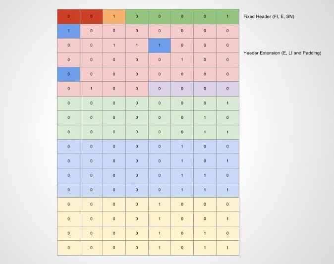
Bit confused? Let’s take each byte and check what it represents.
Fixed Header Part
| Description | |
|---|---|
| FI | 00 First byte of the Data field corresponds to the first byte of a RLC SDU. Last byte of the Data field corresponds to the last byte of a RLC SDU. |
| E |
1 A set of E field and LI field follows from the octet following the fixed part of the header |
| SN | 00001 We assume that this is the first PDU to be transmitted. So Sequence Number is 1 |
Header Extension Part
1000 0000
0011 1000
0000 0100
0000 0000
0100 0000
| Description | |
|---|---|
| For first SDU |
E = 1
LI = 0000 0000 011 |
| Second SDU | E = 1
LI = 0000 0000 100 |
| Third SDU | E = 0
LI = 0000 0000 100 |
| Padding | 0000 |
The rest part of the PDU is data.
Acknowledged Mode Data PDU (AMD PDU)
RLC AM is used both in user plane and control plane packets. But in both the cases PDCP is the upper layer. So all the SDUs which come to RLC AM entity are security protected.
RLC AM supports HARQ mechanism to retransmit lost PDUs. The entity also supports segmentation and concatenation.
The fixed part of the AMD PDU segment header itself is byte aligned and consists of a D/C, a RF, a P, a FI, an E, a SN, a LSF and a SO. The extension part of the AMD PDU segment header itself is byte aligned and consists of E(s) and LI(s).
NOTE: LTE RLC AMD PDU Sequence Number (SN) is 10 bits long.
When in the header extension part odd numbers of E(s) and LI(s) pair are present, four padding bits are added after the last LI. (Check example)
Let’s check how AMD PDU looks like for various cases:
AMD PDU (No LI)

AMD PDU (Odd number of LIs)

AMD PDU (Even number of LIs)

Example: AMD PDU Odd number of LIs

Let’s discuss how AMD PDU is encoded when there are odd number of SDUs (LIs) transmitted in the same RLC PDU. We will use the same SDUs we used for UMD PDU encoding example.
RLC AM SDUs:
01 02 03
04 05 06 07
08 09 10 11
There are three RLC SDUs here which need to be concatenated into one RLC PDU and eventually this will be sent to the lower layer i.e. MAC.
Let’s assume that the PDU is the first RLC PDU which is going to be transmitted. So the Sequence Number (SN) of this RLC MD PDU is 1.
Fixed Header:
1000 0100 0000 0001
| D/C | 1 (Data PDU) |
|---|---|
| R/F | 0 |
| P | 0 (We assume no polling is requested) |
| FI | 00 |
| E | 0 (E and LI field follows) |
| SN | 00 0000 0001 (First PDU to be transmitted) |
Header Extension:
1000 0000
0011 1000
0000 0100
0000 0000
0100 0000
These are a set of E(s) and LI(s) followed by 4 bits of padding.
After this the rest part of the PDU are the RLC SDUs.
AMD PDU segment
AMD PDU segment header consists of a fixed part (fields that are present for every AMD PDU segment) and an extension part (fields that are present for an AMD PDU segment when necessary). The fixed part of the AMD PDU segment header itself is byte aligned and consists of a D/C, a RF, a P, a FI, an E, a SN, a LSF and a SO. The extension part of the AMD PDU segment header itself is byte aligned and consists of E(s) and LI(s).
I will discuss about AMD PDU Segment in a separate post.
AMD PDU Segment header structure

RLC STATUS PDU
RLC ŚTATUS PDU is sent from the receiver to the transmitter in order to provide the status of the PDUs which are correctly received and which are lost during transmission. The transmitting side after receiving the STATUS PDU, removes the PDU which are correctly received at the receiver from the retransmission buffer. It also retransmit all those PDUs which are not correctly received at the receiver.
In UMTS many different types of RLC Control PDU types were used. But in LTE the STATUS PDU concept is now simplified and only one type of control PDU type is used. But still for future use there exists a CPT (Control PDU Type) field.
Let’s check how a RLC STATUS PDU look like:

Parameters in RLC PDUs
Data Field: All the SDUs coming from the upper layer are mapped to this field. But the length of the Data Field depends on this simple formula:
Data Field Length = MAC Transport Block Size Configured – MAC Header Size – RLC Header Size
Sequence Number (SN)
The SN field tells the sequence number of the RLC UM and AM PDUs. This is used for proper concatenation of the PDUs in case RLC UM and AM. Additionally, for RLC AM sequence number can be used for HARQ process (Recovering and retransmission of lost PDUs)
SN field is of 10 bits long for RLC AM and for UM it ca be configured to 5 bits or 10 bits.
Extension bit (E)
Similar to UMTS the extension bit represents if whether Data field follows or a set of E field and LI field follows. Here is how E bit is used in fixed part of the header and in extension part of the header.
For fixed part
0 – Data field follows from the octet following the fixed part of the header
1 – A set of E field and LI field follows from the octet following the fixed part of the header
For extension part
0 – Data field follows from the octet following the LI field following this E field
1 – A set of E field and LI field follows from the bit following the LI field following this E field
Length Indicator (LI)
The LI field indicates the length in bytes of the corresponding Data field element present in the RLC data PDU delivered/received by an UM or an AM RLC entity.
As we discussed in the example, each RLC SDU received can have a LI associated with it.
Framing Info (FI)
This is a new field in LTE RLC. This field tells cleverly tells whether a RLC SDU is segmented at the beginning and/or at the end of the Data field.
| Value | Description |
|---|---|
| 00 |
First byte of the Data field corresponds to the first byte of a RLC SDU. Last byte of the Data field corresponds to the last byte of a RLC SDU. |
| 01 |
First byte of the Data field corresponds to the first byte of a RLC SDU. Last byte of the Data field does not correspond to the last byte of a RLC SDU. |
| 10 |
First byte of the Data field does not correspond to the first byte of a RLC SDU. Last byte of the Data field corresponds to the last byte of a RLC SDU. |
| 11 |
First byte of the Data field does not correspond to the first byte of a RLC SDU. Last byte of the Data field does not correspond to the last byte of a RLC SDU. |
Segment Offset (SO)
The SO field indicates the position of the AMD PDU segment in bytes within the original AMD PDU.
Last Segment Flag (LSF)
LSF is 1 bit long. The LSF field indicates whether or not the last byte of the AMD PDU segment corresponds to the last byte of an AMD
PDU.
0 – Last byte of the AMD PDU segment does not correspond to the last byte of an AMD PDU.
1 – Last byte of the AMD PDU segment corresponds to the last byte of an AMD PDU.
Data or Control (D/C)
This field tells if the PDU is a data PDU or a STATUS PDU (RLC control PDU).
0 – Control PDU
1 – Data PDU
Re-segmentation Flag (RF)
This is a 1 bit long field which tells if RLC PDU is an AMD PDU or AMD PDU Segment.
0 – AMD PDU
1 – AMD PDU segment
Polling Bit (P)
The polling bit tells if transmitting side RLC is requesting the receiving entity about the status of previously transmitted PDUs.
0 – Status report not requested
1 – Status report is requested
Reserved 1 (R1)
These bits are reserved for future version of the protocol. It is always set to 0.
Control PDU Type (CPT)
In LTE there is only one Control PDU type, i.e the STATUS PDU. But still there is a 3 bits long field used for identifying the type. This is most probably reserved for future version of the protocol.
000 – STATUS PDU
001-111 – Reserved (PDUs with this coding will be discarded by the receiving entity for this release of the protocol)
Acknowledgement SN (ACK_SN)
The ACK_SN is a 10 bits long field which indicates indicates the SN of the next not received RLC Data PDU which is not reported as missing in the STATUS PDU.
Extension bit 1 (E1)
The E1 field indicates whether or not a set of NACK_SN, E1 and E2 follows.
0 – A set of NACK_SN, E1 and E2 does not follow.
1 – A set of NACK_SN, E1 and E2 follows.
Negative Acknowledgement SN (NACK_SN)
The NACK_SN field indicates the SN of the AMD PDU (or portions of it) that has been detected as lost at the receiving side of the AM RLC entity.
Extension bit 2 (E2)
The E2 field indicates whether or not a set of SOstart and SOend follows.
0 – A set of SOstart and SOend does not follow for this NACK_SN.
1 – A set of SOstart and SOend follows for this NACK_SN.
Hope this tutorial on LTE RLC PDU headers encoding will help you to understand the protocol better. If you still want to know more about LTE RLC or any other protocol feel free to ask in the comment section or send just your questions to contact@3glteinfo.com.